Home>>Products>>IP for HERON-FPGA modules>>CameraLink with FPGA
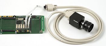
CameraLink Interface with HERON-FPGA Modules
- Standard IP that you can download to an HERON-FPGA module to implement a generic area-scan camera interface for connecting to a Camera Link™ camera
- VHDL sources so that you can add your own FPGA design to this interface which uses only 20% of the FPGA logic
- Offers automatic frame-size and region of interest detection plus programmable region of interest for capture and frame capture control
The Camera Link Area-scan Camera IP supplied by HUNT ENGINEERING provides a structured starting point for the development of an area-scan camera interface. The example IP includes several components suitable for processing a stream of camera data. Part of the IP, AUTO-ROI, performs automatic region of interest detection. AUTO-ROI allows the frame size and active areas of the image to be detected automatically and read over the Heron Serial Bus (HSB) message interface. Using HSB messages, RS-232 communication can also be performed with the camera.
The standard IP outputs full rate image data via a HERON FIFO. This means the data can be accepted by another FPGA module or a C6000 module.
There is a C6000 example supplied with the IP that captures the image data into the module memory. The C6000 then formats this into Windows .bmp format and writes it to the hard drive of the host PC.
Camera pixel rates of up to 24Mhz can be used with the standard IP, but the VHDL sources include the correct code that can be compiled for higher pixel rates.
Note on Hunt Engineering CameraLink Examples
The CameraLink connection is a standard, and the HUNT ENGINEERING VHDL will receive data from that standard connection.
The standard allows for Base, Medium and Full configurations, which means one, two or three camera link cables connected between your camera and the
framegrabber.
HUNT ENGINEERING's VHDL implements the Base configuration only. It is possible to extend this to use
Medium or Full configurations yourself, by changing/adding VHDL.
Each cable connection carries 28 bits of data, which can carry different data connections according to the camera. It might be 8 bits only used for a simple monochrome camera, could be 10 or 12 bits for a camera with more dynamic range, or could even be RGB for a colour camera.
Our VHDL examples use 8 bits of monochrome data only. It is possible to extend this to use more bits and/or colour yourself, by changing/adding VHDL.
Cameras can be either Area-scan (like a TV camera) where a fixed area is imaged repeatedly, or
Linescan where a single side to side line is scanned repeatedly. The linescan is used to make an image of something that is moving like a production line. In this case there is a continuous stream of lines, and no framesync, because the image is one long image formed over time.
Our VHDL examples use an AreaScan camera only. It is possible to extend this to use a linescan camera yourself, by changing/adding VHDL.
In summary, the examples use an 8 bit monochrome area scan camera, connected using CameraLink Base configuration. All other configurations are supported by the CameraLink interface that we provide, but if you need the examples to work with a different configuration you need to make changes to support the exact configuration you need.
Functional Block Diagram
HERON-FPGA3, HERON-FPGA5, HERON-FPGA7, HERON-FPGA9, HERON-FPGA12 and HERON-FPGA14 modules are all suitable for use as CameraLink interface.
![]() CameraLink
Camera Interface with FPGA
CameraLink
Camera Interface with FPGA
(opens in new window)