Home>>HERON modular systems>>Imaging with FPGAs
Imaging with FPGAs
The HERON-FPGA family is ideal for many of the building
blocks of digital systems. Providing
large easily programmed gate arrays, often combined with interface elements like
ADC or DACs, they can be used to implement many system components.
A popular use of HERON real time systems is to perform image processing. This is
really integer processing and lends itself very well to using an FPGA.
This note discusses the issues that must be considered when using a HERON-FPGA
system for image processing.
It references the separate Imaging with FPGA demo/framework that is provided
with HERON systems to give users wishing to build an image processing system a
starting point and the VHDL to perform many of the standard Image processing
functions.
What is Image Processing?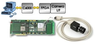
The images that we are used to seeing from video and
still cameras are reproducing the information that we see with our eyes. The
human brain is able to process a lot of detail such as colour, texture and
shape.
The machine vision systems that are often used in security, quality control and
automatic handling systems etc are not as clever as the human brain at using the
information in a raw image. What they are clever at is performing the same task
consistently and quickly.
Image processing is used to allow a “computer system” to extract
information from the incoming images. Actually there are a small number of image
processing techniques that make up the image processing part of all such
systems.
Image Acquisition
In a HERON system the digital images can come from a
variety of sources. Images can be passed into the system from the Host Computer
using the HERON-FIFOs – thus the system can be used to post process stored
images. Images can also be acquired directly from a sensor such as a video
camera. HUNT ENGINEERING offers VHDL Intellectual Property that allows a user to
connect a CameraLink digital video camera directly to a HERON-FPGA module. Analogue cameras could
just as easily be connected using a module that combines some video A/Ds and an
FPGA.
In all of these cases it is easy to obtain a digital video data stream in an
FPGA.
An image stream coming from a camera can be free running, or triggered (where
the generation of an image is triggered by an external event). Images coming
from disk will arrive at varying rates according to Disk speeds, PCI bus
response etc. This means that the image processing has to use some scheme to
enable when there is valid data to process. This can be used to prevent the
processing using values from blanking or synchronisation periods, and will
ensure that the processing is not made during cycles where no image data is
available.
Colour Format
Machine vision systems rarely process colour images.
Those that do will often be merely detecting the presence of a colour or range
of colours – an operation that it is very simple to do in an FPGA.
Some sensors offer RGB component video, others formats like YUV or HSI. Systems
may be able to use one or all of these formats for image processing. You can
convert digital video from one format to another with some well defined
mathematical operations – again perfect for an FPGA.
Most machine vision systems however actually use Monochrome (black&white)
images. This is what we concentrate on in the remainder of this document.
Pixel Operations
Some image processing functions operate on a single
pixel at a time. These can be additions, multiplications, thresholding etc,
where the same operation is applied to each and every pixel in an image,
resulting in a new value for that pixel. This type of operation is almost
trivial to perform in an FPGA, and can normally be performed at very high data
rates (>500M pixel/sec). These functions can be performed on the stream of
data as it arrives, so the processing speed will normally be governed by the
incoming data rate.
This is a contrast to when you use a processor based approach where the
processor has to receive the data, perform the manipulation and store the result
– then such a pixel by pixel operation consumes a large amount of processor
resources.
Multi Frame Processing?
An often used technique is to manipulate the pixels in
an image according to their position in that image. This could be a calibration
type of feature, or an operation using a reference frame e.g. subtracting a
standard frame from the incoming frame so that any pixels that have not changed
become close to zero.
This type of function requires a stored image, that can be accessed at the same
time as the incoming image. Unless the image is very small in size, the RAM
resources of the FPGA are not going to be enough for this type of operation.
Then hardware like the HERON-FPGA5 and
related modules can be used. The stored image will then be stored in SDRAM that
is external to the FPGA.
These operations can also be performed at very high pixel rates
(>450Mpixels/sec) as the accessing of the SDRAM, the incoming image, and the
output of results will all use dedicated hardware resources of the FPGA to
perform the operations in parallel.
Contrasting that with a processor based approach, the processor has more memory
accessing to perform in multi-frame processing, and it is likely that these
operations will be slower than the pixel based operations when using a
processor.
Neighbourhood Processing
A further type of image processing function uses a
region of the image to produce a single output pixel. The most common of these
operations is a convolution, where a mask of co-efficients are used to
“weight” each pixel value. The result is then scaled to produce a pixel
output. This is essentially a matrix multiplication operation.
Multiple multiply and accumulate operations are needed for each pixel. The exact
number is determined by the mask size, but even the smallest convolution with a
mask size of 3x3 requires 9 multiplies and 9 additions. In an FPGA you can use 9
multipliers and 9 adders to perform this, whereas a processor will not have this
amount of resources so will require multiple processor clocks to calculate each
pixel value.
The operation of a convolution can be defined by the co-efficients used.
Detection of edges is a common use, and horizontal, vertical or diagonal edges
can be emphasised by choosing different co-efficient sets for the same processing
operation. High and low pass filtering can also be achieved simply by using
different co-efficients.
The HUNT ENGINEERING image processing VHDL functions offer a generic convolution
function for 3x3 and 5x5 kernels, where the co-efficients can be programmed at
run time. Larger kernel sizes can easily be achieved by extending the supplied
VHDL to meet your needs. The provided functions can still operate at
>100Mpixels/second limited by the speed of the Virtex®-II multipliers.
However several standard co-efficient sets can be found in a few minutes of research on the internet. Standard filters like Sobel actually use co-efficients
that are 1,2,-1,-2 and 0. If you use a processor, the only optimisation that can
be made is that a co-efficient of 0 need not be calculated, but in a hardware
implementation such as that of an FPGA, multiples of 1,2,-1 and –2 can be made
by simple shifts, that come free by routing the FPGA design in the correct way.
Thus the HUNT ENGINEERING image processing VHDL is able to implement Sobel,
Prewitt, Laplacian and similar functions without the need for any multipliers.
This brings a huge advantage to the FPGA version because very little of the FPGA
is used for these standard convolutions and speeds of more than
200Mpixels/second can be achieved.
Neighbourhood processing requires several lines of image data to be stored
before processing can begin. The image size determines the amount of storage
required to store a line of image, and the kernel size of your neighbourhood
operation determines the number of lines that need to be stored. It may be
possible to use the Block RAM that is internal to the FPGA for this storage, but
the amount available depends on the size of FPGA you are using and what else in
your design required Block Rams. As an example, a 1M gate Virtex®-II FPGA has
90Kbytes of Block RAM. If nothing else in your design requires Block RAMs then
you can make a convolution on 90Kbytes of image. Actually you will need space to
continue storing incoming data, so we could assume an extra line buffer could be
needed. Even so 90Kbytes could be 90Kpixels if we use 8 bit monochrome pixels,
so if our image is 2K pixels (a large image) we can store 45 lines of data. That
is a huge Convolution function!
The real problem comes when in fact your FPGA design uses Block RAMs for other
functions. Then it can be interesting to use hardware like the HERON-FPGA5 where
the image can be stored in the off chip SDRAM. In that case regions of the data
must be carefully brought into some internal RAM buffers if you want to achieve
high data rates, but this is quite possible. HUNT ENGINEERING provide an example
that shows you how to do that by carefully managing the SDRAM.
Outputting the Results
The output from a machine vision application can be in
many different formats. If your decision cannot be taken by logic in the FPGA,
you may have to output the processed image data. In a HERON system this output
will be via the HERON-FIFOs, which like any other storage mechanism have a
limited storage capacity. Depending on the access at the other end of the FIFO,
the FIFO may become full. It is important that your system design includes a
strategy for what to do if that occurs.
The time that this is most often encountered is when transferring the results of
your processing to the Host PC. This transfer will take place across the PCI
bus, and will ultimately be controlled by the Device Drivers and Operating
System that is running on the Host PC. Although you might be able to average
>100Mbytes/second from your system to the PC, it will actually be made as
bursts of 132Mbytes/second with periods in between where no transfers happen
(0Mbytes/second). It is during those periods of 0Mbytes/sec that your FIFO runs
the risk of overflowing. Windows for example is not a real time operating system
and doesn’t make any guarantees of response to interrupts or scheduling of
device drivers. Windows documentation admits that the interrupt response times
can be greater than 100ms! If your imaging system is generating data at only
10Mbytes/second, this means that a buffer of 1Mbyte is needed to store data
while Windows is not responding.
Depending on your application you might be able to accept the loss of images,
but a FIFO overflow will not lose a whole image, but rather parts of an image
The Imaging with FPGA demo/framework provided by HUNT ENGINEERING actually uses
the technique of accepting the loss of frames from time to time. Each image is
carefully checked by the host program and only complete frames are displayed.
There are Frame and Line markers embedded in the image data specifically to
allow this type of checking.
While this is acceptable in circumstances like the demo where the image is
simply displayed to a user, other applications may need to prevent the loss of
data altogether. Then it is really important to use a module like the
HERON-FPGA5 where the off chip SDRAM can be used to buffer data for outputting
to the PC. Then when the PC doesn’t respond the data will be stored and not
lost. When the PC starts to respond again the buffer will be flushed across to
the PC. Thus the Windows non-real time behaviour simply becomes a variable
latency rather than causing a loss of data.